Different Types of Meshes in CFD
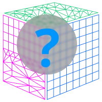
Computational Fluid Dynamics (CFD) relies heavily on the accuracy of spatial discretization. This process, commonly known as meshing, transforms the fluid domain into a collection of smaller control volumes or elements. These elements enable the governing equations of fluid flow to be numerically solved with reasonable accuracy and computational efficiency.
The selection of mesh type is a critical decision that influences the fidelity of simulation results, solver performance, and turnaround time. Depending on the geometry, flow physics, and computational resources, engineers must choose an appropriate mesh type or a combination of types. This article explores the different categories of meshes used in CFD, highlighting their properties, advantages, and limitations in detail.
Classification Based on Element Shape
At the core of mesh generation is the shape of the individual elements. These shapes determine how well the mesh conforms to the geometry, the flow direction, and how accurately gradients and physical quantities are captured.
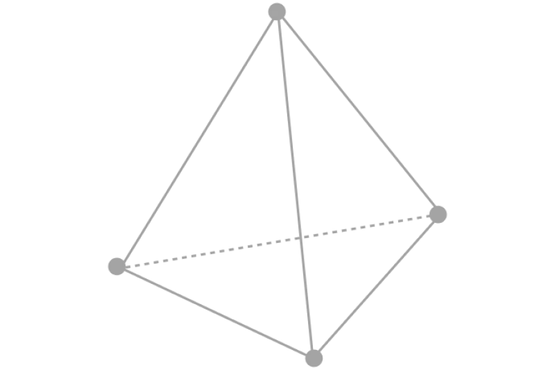
Tetrahedral Elements
Tetrahedral elements are four-faced polyhedra with triangular faces. These elements are particularly valuable when meshing highly complex and organic shapes, where automatic mesh generation is essential. Because of their isotropic nature, tetrahedra can fill irregular geometries uniformly without manual intervention.
However, tetrahedra come with inherent drawbacks. Their inability to stretch significantly makes them unsuitable for resolving thin layers near walls, such as viscous boundary layers. Excessive stretching leads to highly skewed cells, which degrade numerical stability and solver performance. Furthermore, because tetrahedra do not align naturally with the direction of flow, they introduce more numerical diffusion compared to hexahedral elements.
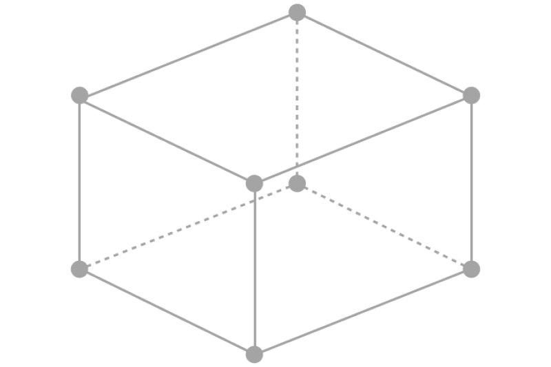
Hexahedral Elements
Hexahedral elements resemble cubes or rectangular bricks and are considered the gold standard for CFD simulations. These elements exhibit superior numerical properties, particularly when aligned with the flow direction. Their structured nature ensures minimal numerical dissipation, leading to high solver accuracy and faster convergence.
The generation of hexahedral meshes, however, is not trivial. For complex domains, manual block decomposition is often necessary to facilitate mesh generation. This makes the process labor-intensive and time-consuming, especially when geometric intricacies or topology transitions are involved.
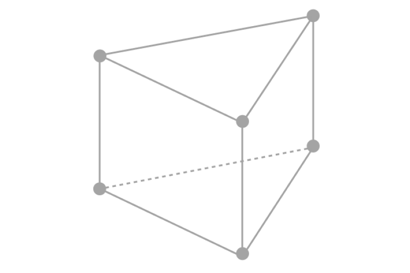
Prism Elements
Prism elements are essentially extruded triangles, forming three-sided prisms with rectangular faces. These elements are especially useful in boundary layer regions where anisotropic stretching is required. Their vertical structure allows for height-wise stretching normal to the wall while maintaining good element quality.
Prisms offer better control over aspect ratio than tetrahedra and are a popular choice in hybrid mesh strategies. They bridge the gap between structured efficiency and unstructured flexibility by allowing directional control in boundary layer regions.
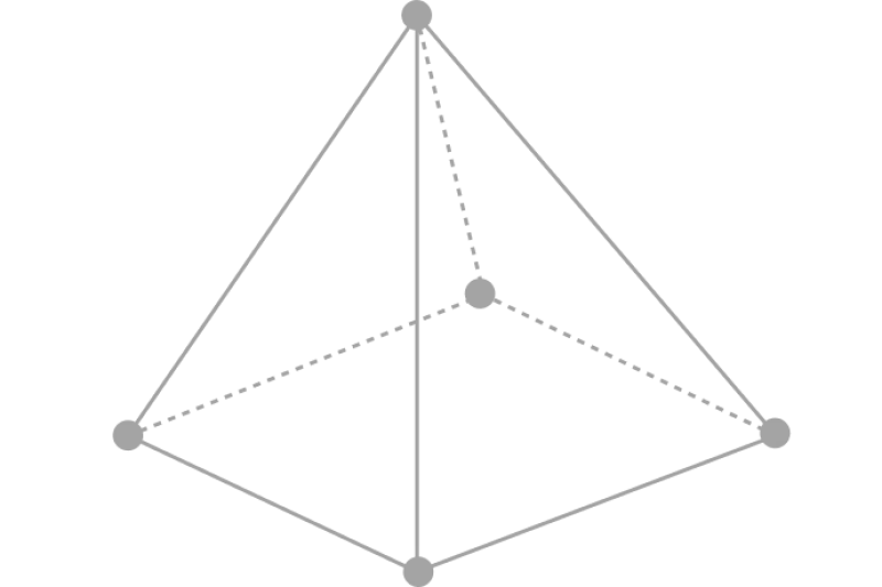
Pyramids Elements
Pyramids are five-faced elements used as transition elements between tetrahedra and hexahedra. These are essential in hybrid meshing where different regions of the domain are meshed using different element types.
Although pyramids are used sparingly, their presence is crucial in maintaining a coherent and conformal mesh structure across zones with varying element shapes. Care must be taken to avoid poor-quality pyramids that may deteriorate numerical accuracy.
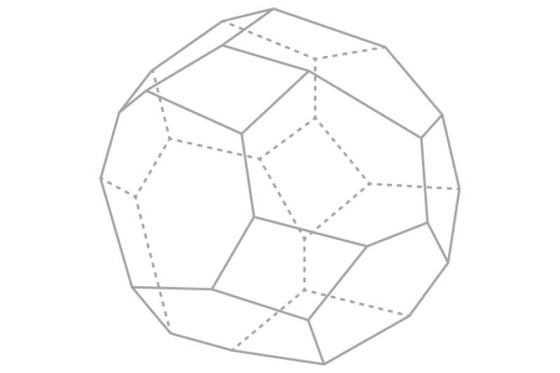
Polyhedral Elements
Polyhedral meshes consist of cells with a high number of faces, often generated by merging smaller tetrahedral elements. These complex elements offer an ideal balance between mesh quality and computational efficiency. Unlike tetrahedra or hexahedra, polyhedra can naturally adapt to irregular domains while maintaining better internal angles and smoother transitions.
A key advantage of polyhedral cells is their increased face-sharing capability. This results in more neighboring interactions, leading to improved gradient resolution and lower numerical diffusion. Although computationally more expensive per cell, they often require fewer total elements to achieve the same level of accuracy, thereby improving convergence characteristics.
Classification Based on Number of Element Types
Many CFD domains exhibit regions with vastly different meshing requirements. For such scenarios, employing a single type of element throughout the mesh becomes inefficient or infeasible.
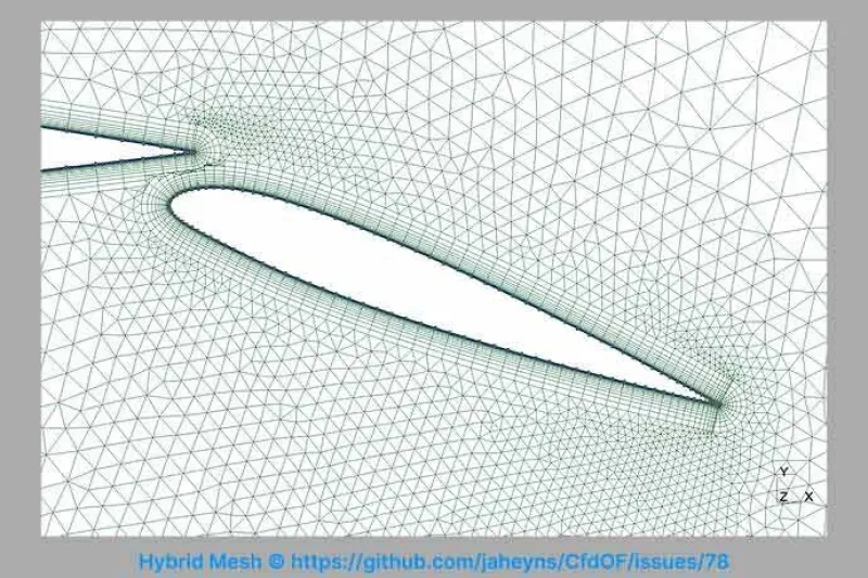
Hybrid Meshes
Hybrid meshes combine multiple element types within the same computational domain. For instance, prism or hexahedral elements may be used near walls to resolve boundary layers, while tetrahedra or Cartesian elements fill the rest of the domain. This mixed approach balances accuracy, cell quality, and ease of mesh generation.
Transitioning between different element types within hybrid meshes is carefully managed using pyramids or transitional polyhedra. This ensures mesh continuity and avoids sudden jumps in element size or shape, which can disrupt solution stability. Hybrid meshes are common in aerospace, automotive, and biomedical CFD where complex geometries demand both geometric fidelity and solver efficiency.
Classification Based on Connectivity
Connectivity between elements or mesh blocks influences the solver's ability to handle variable transitions and compute fluid properties across boundaries.

Conformal Grids
In conformal grids, each element edge or face exactly matches the adjacent element’s boundary. This uniformity leads to simpler numerical schemes since no interpolation is required at the interfaces. Conformal meshes are typically seen in structured grids, where grid lines align and maintain continuity throughout the domain.
Such meshes are desirable for minimizing numerical error and ensuring robust conservation of mass, momentum, and energy. However, achieving conformality in complex domains can be a significant challenge, especially when using structured approaches.
Non-Conformal Grids
Non-conformal grids do not maintain one-to-one correspondence at the interfaces between mesh blocks. These mismatches can arise from differing element sizes, shapes, or refinement levels. While non-conformal interfaces increase flexibility, they require specialized interpolation or projection methods to transfer data across regions accurately.
Although slightly more error-prone, non-conformal grids offer superior adaptability when dealing with highly complex geometries or when mesh refinement is needed only in localized areas.

Classification Based on Cell Type and Arrangement
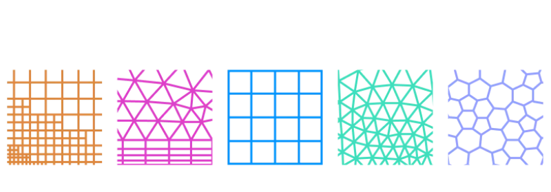
Structured Meshes
Structured meshes are characterized by a regular, grid-like arrangement of cells. These meshes are indexed systematically using a 3D coordinate system (i,j,k)(i, j, k), which allows neighbor identification without storing explicit connectivity data.
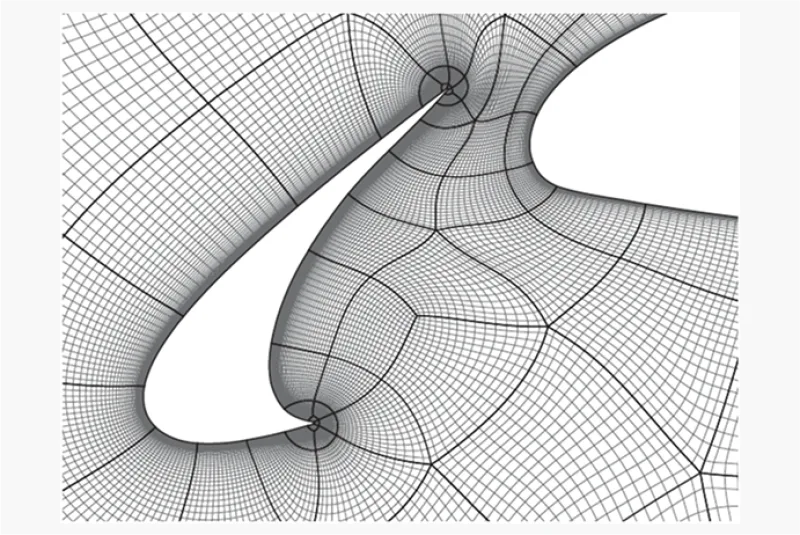
For simple geometries such as ducts, pipes, or airfoils, structured meshes offer unparalleled performance. They allow directional refinement and flow-aligned meshing, reducing numerical dissipation and ensuring fast convergence. Furthermore, due to the predictable arrangement of cells, structured meshes often require fewer cells to achieve the same resolution as unstructured alternatives.
In complex geometries, the domain is divided into multiple blocks (multi-block approach). Each block is meshed independently, and blocks are joined to form a conformal mesh. While this process demands expertise, it enables the creation of high-quality meshes for even moderately complex geometries.
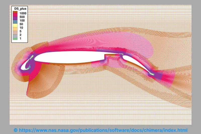
Overset Meshes
Also known as Chimera meshes, allow overlapping of structured blocks. Instead of creating a single continuous mesh, the domain is divided into overlapping grids that communicate through interpolation.
This method is especially useful in simulations involving moving components, such as rotating propellers or flapping wings. It enables local mesh motion without deforming the overall grid. Overset meshes simplify meshing for complex assemblies and facilitate dynamic simulations by allowing relative motion between components.
However, the interpolation between overlapping blocks introduces potential for interpolation errors and increases computational overhead. Careful management of overlapping regions is required to maintain accuracy and conservation.
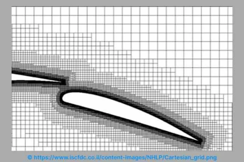
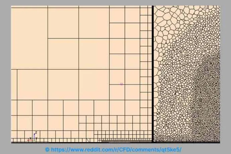
Cartesian Meshing
Cartesian meshing involves filling the domain with hexahedral cells aligned with the global coordinate axes. These meshes are easy to generate and lend themselves well to automation and rapid prototyping.
One of the key benefits of Cartesian meshes is the ease of applying adaptive mesh refinement (AMR), which allows dynamic cell refinement based on flow features such as shocks or vortices. However, near curved surfaces or walls, Cartesian meshes perform poorly due to stair-stepped approximations and poor wall-normal resolution.
To resolve thin boundary layers, Cartesian meshes require excessive refinement in all directions, leading to a rapid increase in cell count. Moreover, hanging nodes—where small cells adjoin larger ones—can destabilize solvers unless special schemes are employed.
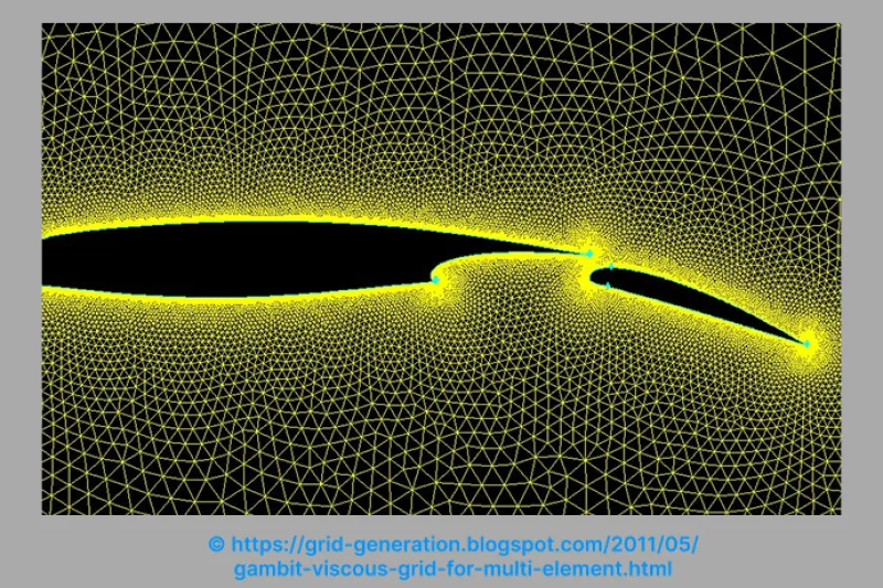
Unstructured Meshes
Unstructured meshes are defined by irregular connectivity between elements. This makes them ideal for automatically meshing geometrically complex domains with minimal user input.
Tetrahedra are the most common unstructured elements, but unstructured meshes can also include prisms, pyramids, or hexahedra. Their flexible nature makes them a preferred choice in automotive, biomedical, and aerospace applications where geometry is often intricate and irregular
The drawback of unstructured meshes lies in their numerical inefficiency. Tetrahedral elements are prone to higher numerical diffusion, and poor alignment with flow can lead to longer convergence times. Additionally, solver performance is often affected by the need to store and access connectivity data.
- Delaunay Triangulation
This technique maximizes the minimum angle of each triangle (or tetrahedron), ensuring well-shaped elements. It is commonly used in automatic meshing tools due to its mathematical robustness.
- Advancing Front Method
Here, meshing begins at the domain boundaries and progresses inward. It provides good surface conformity and boundary layer control but requires careful handling in highly concave or interconnected regions.
- Quadtree/Octree Methods
These hierarchical methods divide the domain recursively into square (2D) or cubic (3D) cells. Refinement is performed based on geometric or flow-based criteria. These methods are ideal for automated meshing but need smoothing or transition layers for curved boundaries.
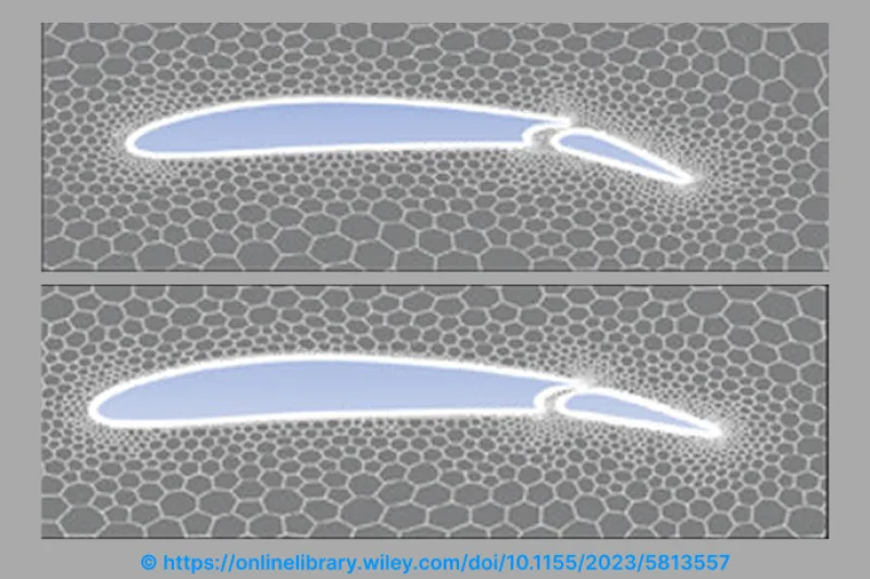
Polyhedral Meshes
Polyhedral meshes extend the unstructured meshing concept by replacing simple elements with cells having many faces. This increases the number of neighboring cells and enhances numerical interactions.
The larger surface area of each cell face improves the gradient computation, which enhances accuracy for transport-dominated flows. Also, polyhedral meshes typically require fewer cells than tetrahedral meshes for the same accuracy, leading to reduced computational cost despite the complexity of each cell.
Polyhedral meshing strikes a balance between solver stability, convergence speed, and geometric flexibility. As such, they are increasingly used in commercial CFD applications that prioritize both speed and precision.
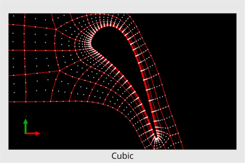
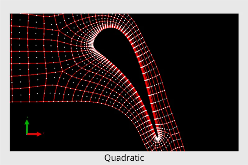
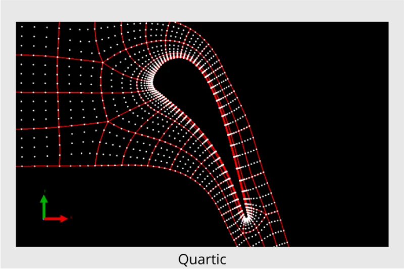
Higher-Order Curved Meshes
Traditional CFD meshes use linear elements. To achieve higher-order spatial and temporal accuracy, linear elements are enhanced by adding internal nodes. This transforms linear cells into curved cells capable of capturing geometry and flow variations with greater fidelity.
These elements are classified based on the number of internal nodes:
- Quadratic: One node per edge
- Cubic: Two nodes per edge
- Quartic: Three nodes per edge
High-order curved meshes are crucial in simulations involving acoustics, vortex shedding, or wave propagation. They enable solvers to use fewer elements while still achieving high resolution, reducing memory requirements and simulation times. However, they demand solvers that can handle curved geometry and complex interpolation schemes.
Conclusion
Meshing is not merely
a pre-processing step in CFD—it is a strategic component that profoundly influences simulation outcomes. From structured and unstructured to hybrid and polyhedral meshes, each type serves specific needs depending on geometry complexity, flow characteristics, and solver capabilities.
A well-chosen mesh improves accuracy, reduces computational cost, and accelerates convergence. Engineers must balance competing priorities—automation vs. control, accuracy vs. speed, flexibility vs. robustness—when selecting or designing mesh types. As CFD technology continues to evolve, so too will meshing strategies, promising even more powerful tools to model the complex world of fluid dynamics.